




The grinding the disc of gate valves process comprises three stages: rough grinding, finish grinding, and polishing. Rough grinding eliminates defects such as scratches, indentations, and pits on sealing surfaces, achieving high flatness and precise surface roughness to prepare for finish grinding. This stage employs coarse-grit abrasives (paper or cloth) with 80-280 grit particles. While offering high efficiency and significant cutting capacity, this method creates deeper abrasive patterns that leave sealing surfaces relatively rough, necessitating subsequent finish grinding.
Understanding the Process of Grinding the Disc of Gate Valves
Precision grinding is performed to eliminate surface roughness on sealing surfaces, thereby enhancing their flatness and surface roughness accuracy. This process utilizes fine-grained sand cloth or abrasive particles (280-grit or W5) with minimal cutting depth, which effectively improves surface finish precision. When performing precision grinding after rough grinding, the abrasive tool should be replaced with one that offers higher flatness than the initial roughing stage, and the tool must be thoroughly cleaned. For standard valves, precision grinding typically meets final technical requirements. However, valves demanding higher surface roughness precision require additional polishing. Manual grinding, whether for rough or precision stages, involves continuous operations combining lifting, lowering, rotating, reciprocating, tapping, and directional changes. This comprehensive process prevents abrasive particle trajectory repetition, ensuring uniform grinding of both the tool and sealing surface to improve flatness and surface roughness accuracy.
Inspection runs through the grinding the disc of gate valves process, the purpose is to grasp the grinding situation at any time, so as to have a clear mind, so that the grinding quality meets the technical requirements.
Local grinding of the plane sealing surface Local grinding is mainly manual grinding, and dry grinding is used more. The purpose of local grinding of the plane sealing surface is to eliminate the local protrusion on the sealing surface and correct the improper angle between the two sealing surfaces.
There are many local grinding methods for planar sealing surfaces, as shown in Figure 9-15.
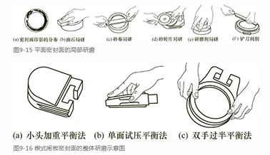
The distribution of the imprint on the sealing surface is shown in ①Figure 9-15 (a). The defect on the sealing surface is reflected by the inspection of a standard plate or standard grinding tool. It is necessary to prevent the use of a plate or grinding tool with low flatness for inspection. Otherwise, the imprint will not be correct.
Regarding the distribution of impressions: The white dot in the upper left corner is a bright spot created by dye penetrant inspection. This area differs from the dullness of unimpressed blank spaces, making it the most prominent. Areas with unclear impressions or excessive developer application are considered lower. The lowest points are those where impression lines break without developer contact. Analysis shows the sealing surface slopes from the lower right corner to the upper left, caused by the protruding white dot. Simply grinding off this upper-left dot will significantly improve the sealing surface’s flatness.
The method developed by the Oilstone Bureau is shown in ②Figure 9-15 (b). A rectangular oilstone is placed flat on a smooth surface, and it is held steadily by hand.
When using an oilstone, naturally press your index finger onto it to control the grinding pressure. This allows the stone to oscillate left and right or move in an arc-shaped reciprocating motion across specific areas until an ideal sealing surface is formed. During the grinding process, apply lubricants such as engine oil or linseed oil to enhance quality and prevent surface roughening.
As shown in Figure 9-15(c) ③, the sanding method using a sandpaper pad is demonstrated. The long board serves as the grinding tool, with sandpaper or sand cloth placed underneath. One end of the board is pressed against the sealing surface by the thumb, while a layer of cloth or paper acts as a fixed point in the middle. The other end is held between the thumb and index finger, pressing down on the sandpaper or sand cloth. During the grinding process, the fingers move left and right, allowing precise control over the grinding speed, pressure, and range through finger movement.
④ Figure 9-15 (d) shows the method of local grinding with a grinding wheel, which is a thin grinding wheel or a single beveled grinding wheel. The operation method is similar to that of long board grinding. This method is efficient and suitable for large local grinding parts.
As shown in Figure 9-15(e) ⑤, the localized grinding method involves evenly distributing abrasive material across a flat surface. The valve disc and gate are manually clamped and placed flat on the abrasive-coated plate. Applying finger pressure to specific areas, the workpiece undergoes an 8-shaped grinding motion with continuous directional changes, ensuring uniform wear across all surfaces. Due to varying pressure distribution on the abrasive particles, different areas experience distinct grinding depths. Areas receiving higher pressure demonstrate faster grinding speeds and naturally formed transitional lines at the localized grinding points.
As shown in Figure 9-15(f) ⑥, the method involves using a scraper to apply red lead, blue lead, and other revealing agents onto the sealing surface to ensure tight adhesion. After forming a latent image, the high points on the sealing surface are scraped using a scraper based on the distribution of the latent image. Through repeated scraping, the sealing surface achieves the desired flatness and surface roughness.
